Chingtek Electronics Corp. |
6-2 |
6-3
|
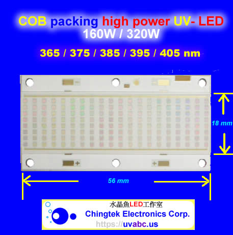
UV LED - 160W - COB type
(UVA 365nm - 415nm )
| ----- Key Features ----- | |
|---|---|
| - | Supply wide UV-A wavelength from 365nm to 430nm |
| - | Over 5W/cm2 of Optical power typical from 390nm to 430nm |
| - | High thermal conductivity package: |
| > Junction to heat sink thermal resistance of < 0.3°C/W | |
| - | High radiometric efficiency |
| - | Environmentally friendly: RoHS compliant, mercury-free |
| - | Variable drive currents: less than 4.5A through 6A |
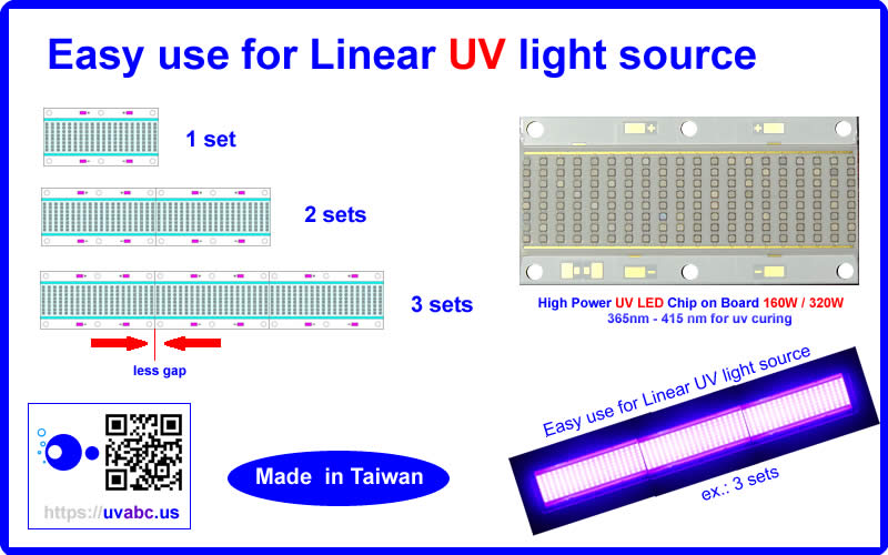
| - | Easy use for Linear UV light source |
| ----- Applications ----- | |
|---|---|
| - | Curing: |
| > Inks > Coatings > Adhesives | |
| - | Inspection |
| - | Machine Vision |
| - | Fiber-coupled illumination |
| - | Specialty Projection Systems for Maskless Lithography |
| - | Rapid Prototyping and 3D printing |
| - | Medical and Scientific Instrumentation |
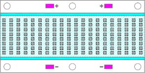
| Package Dimensions (mm) : |
|---|

LED Array: 8s20p / Typical Voltage: 28V / Operating Current: 6000mA
Notes: (1) All dimensions are in millimeters. (2) Tolerance is ±0.25mm
| Technology of Overviews |
|---|
| The COB Multi-chips LED package benefit from innovations in device technology, chip package and thermalmanagement. This suite of technologies give engineers and system designers the freedom to develop solutions both high in power and efficiency. | ||
The Technology |
Reliability Technology |
|
our technology enables to emit large area photons uniformly over the entire COB UV LED surface. The intense optical power density produced by these multi-chips facilitate designs which replace mercury lamps where arrays of traditional power LEDs cannot. |
Designed from the ground up, the COB Multi-chips LEDs are one of the most reliable light sources in the world today. COB Multi-chips LEDs have passed a rigorous suite of environmental and mechanical stress tests, including mechanical shock, vibration, temperature cycling and humidity, and high current applications. With very low failure rates and median lifetimes that typically exceed 10,000 hours, the COB Multi-chips LEDs are ready for evern the most demanding applications. | |
| For UV devices, the side-less structure to let the engineers easy to design the linear UV LED light source and instead of the linear mercury lamps with power density 80W/cm -120W/cm. | ||
Packaging Technology |
Environmental Benefits |
|
| Thermal management is critical in high power LED applications. The UV LEDs have the lowest thermal resistance of any LED on the market with a thermal resistance from junction to heat sink of 0.3°C/W or 0.35°C/W. This allows the LED to be driven at higher current densities while maintaining a low junction temperature, thereby resulting in brighter solutions and longer lifetimes. | our LEDs help reduce power consumption and the amount of hazardous waste entering the environment. All COB Multi-chips LED products manufactured by us are RoHS compliant and free fo hazardous materials, including lead and mercury. | |
| The Advantages of COB Multi-chips LEDs |
|---|
| Every LED is fully designed to ensure that it meets the high quality standards expected from our products. | |
| >>> | Low Thermal Resistance <0.16°C/W / High thermal conductivity 401W/(m.K) |
| Copper Substrate and LED Chip Direct Bonding on Cu Base | |
| >>> | Special Reflecting Surface |
| No Ag Plating, Anti-Sulfide, and Low Light Decay. | |
| >>> | Ni Coating at the Cu substrate bottom |
| Anti-Oxidized and SMT Compatible. | |

| Electrical/Optical Characteristics (Ta=25°C) |
|---|
Optical Characteristics (Ta=25°C) |
|---|
Parameter |
Symbol |
Wavelength |
Conditions |
Min. |
Typ. |
Max. |
Units |
Irradiance Note[1] |
Ee |
365-370nm |
IF=6000mA |
0.25 |
0.5 |
- |
W/cm2 |
370-380nm |
0.5 |
0.75 |
- |
||||
380-390nm |
3 |
3.4 |
- |
||||
390-410nm |
4 |
5.5 |
- |
||||
View Angle |
2θ1/2 |
X-Axis |
IF=6000mA |
140 |
150 |
160 |
Degree |
Y-Axis |
120 |
130 |
140 |
Electronic Characteristics (Ta=25°C) |
|---|
Parameter |
Symbol |
Conditions |
Min. |
Typ. |
Max. |
Units |
Forward Voltage |
VF |
IF=6000mA |
26 |
- |
30 |
V |
Reverse Current Note[1] |
Ir |
VR=5V |
10 |
uA |
||
Thermal Resistance JunctionTo Board |
RthJ-B |
IF=6000mA |
0.1 |
°C/W |
||
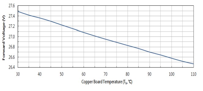
Temperature Coefficient of Forward Voltage |
ΔVF/ΔT |
IF=6000mA |
-64 |
- |
mV/°C |
Absolute Maximum Rating (Ta=25°C) |
|---|
Parameter |
Symbol |
Conditions |
Units |
Power Dissipation |
PD |
200 |
W |
Continuous Forward Current |
IF |
7000 |
mA |
Continuous Forward Current Note[1] |
IF(Peak) |
10,000 |
mA |
LED Junction Temperature |
Tj |
120 |
/°C |
Operating Temperature Range |
Topr |
30℃ To +80℃ |
|
Storage Temperature Range |
Tstg |
-40℃ To +100℃ |
|
Manual Soldering Temperature |
Tsol |
260℃±20℃ For 3-5 Seconds |
|
ESD Sensitivity Note[2] |
ESD |
500V HBM |
|
[2] Singe chip ESD.
| Optical & Electric Characteristics |
|---|
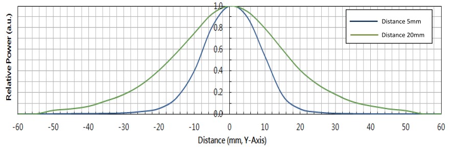
Relative Power vs Distance (at central point ), I F =6000mA

Relative Power vs X-Axis , I F =6000mA

Relative Power vs Y-Axis , I F =6000mA
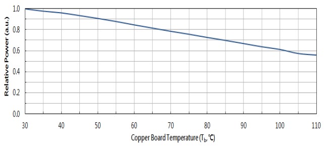
Relative Power vs Board Temperature (Tb )
Forward Voltage vs Board Temperature (Tb )

| UV COB LED Reliability |
|---|
UC-160-VH (B50,L70) Lifetimes @ IF=6000mA

| UV COB LED Spectrum Distribution |
|---|

| Assembly Notice |
|---|
| 1) | Do not touch emitting area. |
|---|---|
| - | Do not touch or scratch silicon forming matrix area since it could damage the bonding |
of LED chipsor wires and cause dead zone. |
|
 Don’t touch the surface of Emitter |
|
| 2.) | Assembly guideline |
| Wiring emitter’s anode/cathode pad, then fix emitter with screws onto heat sink. | |
|
|
| 3.) | Soldering methods |
| a) Set up the temperature of welding head to 400±10℃ when soldering. | |
| b) Put Emitter on a 100±10℃ hot plate and set up welding head temperature to 300±10℃ | |
| c) Either is OK. | |
| 4.) | Wires |
| Suggested using strand wires (softer) to connect power, don’t use solid wires. | |
| Used Notice |
|---|
| 1.) | In order to avoid absorption of moisture, it is recommended that the products are sotred in the dry |
|---|---|
| box (or desiccators) with a desiccants. Alternatively the following environment is recommended. | |
| Storage temperature: 5°C ~ 30°C , Humidity: 60% HR Max. | |
| 2.) | Soldering rapidly cooling should be avoided. |
| 3.) | Products should not be assembly on distorted surface of heat sink. |
| 4.) | Products should not contact with any types of fluid, such as water, oil, organic solvents,...etc. |
| 5.) | The maximum ambient temperature should be taken into consideration when determining the |
| operating current. | |
| 6.) | This product must be driven by constant power supplier. |
| 7.) | ESD Precautions Static Electricity and surge damages LEDs. It is recommended that wrist bands |
| or anti-electrostatic gloves be used when handing the LEDs. All devices, equipment, and | |
| machinery should be properly grounded. | |
| 8.) | The appearance and specifications of product may be modified for improvement without notice. |
| Ordering Information |
|---|
Color |
Order Code |
Peak Wavelength (nm) |
Light Intensity (W/cm2 )@6000mA |
||
Min |
Max |
Min |
Max |
||
UV |
UVA-160-415 |
410 |
420 |
4 |
6 |
UVA-160-405 |
400 |
410 |
4 |
6 |
|
UVA-160-395 |
390 |
400 |
4 |
6 |
|
UVA-160-385 |
380 |
390 |
3 |
4 |
|
UVA-160-375 |
370 |
380 |
0.5 |
0.75 |
|
UVA-160-365 |
365 |
370 |
0.25 |
0.5 |
|
----------------------------------------------------------------------------------------------------------------------------------
-----------------------------------------------------------------------------
| Home | Products | To Order | Photos | Support | Contact |